
| Sway Bar |
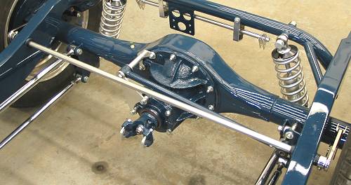
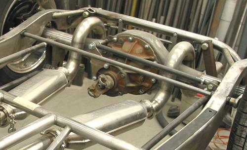
By Frank Colgoni I'm going to try something different with this article. That is, I'm going to show you the finished product first then talk about it. Have a look at the photo below to view the entire rear setup - including the sway bar - spotted it yet? If so, you can see why this solution was chosen. |
Okay, back to the beginning. When it became obvious that a rear crossmember-mounted sway bar was out of the question, John (of Dream Machines) said (as he is apt to say) "we'll get it". Get it he did. To describe the components: a ¾" bar which is bushed near the top of the frame rail and cut to DD ends. At each end, it's attached to a custom made, stainless steel arm which is connected to the axle housing with an adjustable link. With the links being so far out on the axle housing, the bar is very effective. Corners like a Mini. |
 This is the tube that will carry the bushings for the ¾" bar. |
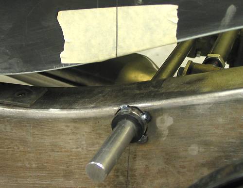 In this photo, the bushings are in place, as is the bar - not cut to length or finished with DD ends. The tape/line on the body marks the centreline of the bar. A rounded notch needs to be cut out of the body to accommodate the arm. |
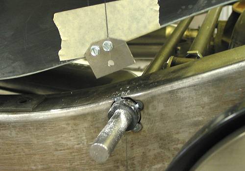 This is a fixture to centre a hole saw to permit a part circle cut. |
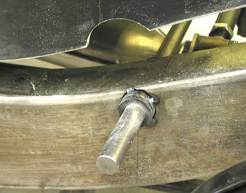 This shows the finished cut. |
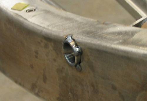
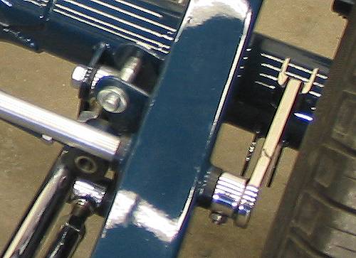 This photo shows the finished arm on the driver's side. A DD coupling was attached to the arm to accept the bar and the forked end of the arm will accept the link. Everything's been polished at this point. The bar has been plated. |
 |
 A look at the arm from another angle with the link in place. |
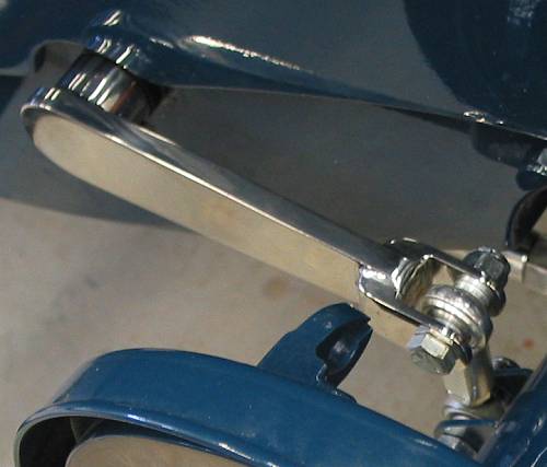
 In this photo you can see where the links attaches to the axle housing. Also, note the neat exit ports that Dream Machines fabbed for the emergency brake cables. |
Resources: |
| Next Up - Inside door handles / mechanisms |
<< Previous
Article -- Next Article>> |
Copyright © Canadian Rodder Inc. / deuceodyssey.com