
| Windshield
Components and Installation |
By Frank Colgoni In this article, we're going to introduce you to windshield components and walk you through the installation on our body. While the windshield components are somewhat common, the actual installation is likely not. That is, it will vary by body and body manufacturer. Windshield Components • a pair of lower stanchions (the uprights that fasten to the body) • a pair of upper stanchions (the extensions that can pivot forward on the lower stanchions - they also anchor a roof header rail) • a windshield frame assembly (upper and lower pieces that separate to fit glass) • two frame studs (studs that thread into the frame that allows the frame to swivel outward at the bottom) • two cones (slips over stud and fits into upper stanchion cup) • four wing nuts (fasten upper stanchion to lower stanchion and terminates stud on upper stanchion) • two rubber insulators (for use between lower stanchions and the body These components are shown in photos that follow - both exploded and assembled. |
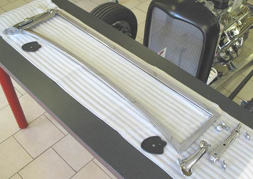 Here's everything laid out. |
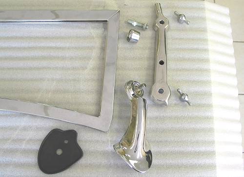 The chrome frame is by Brookville Roadster and features a 3" chop. The chrome lower stanchions, studs, cones and insulators are by Vintique. They stainless upper stanchions (to suit a 3" chop obviously) were sourced by The Old Car Centre. |
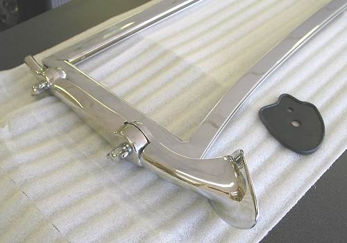 Here's how everything goes together. |
Windshield Installation |
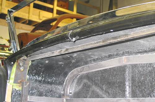
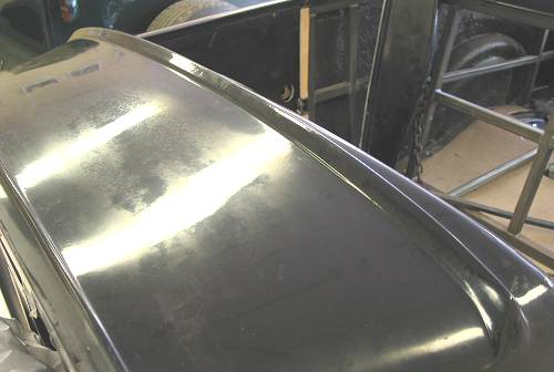 This photo shows the ridge in the cowl. |
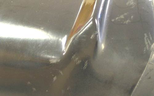 The ridge terminates at each end in a pad area that is meant to mate up with the rubber insulator/lower stanchion. |
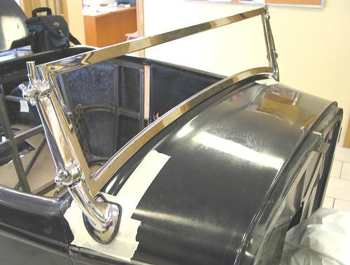
| John (of Dream Machines Ltd.) and I discussed various options relative to first steps. We concluded that, because the windshield frame dictates the overall width of the windshield assembly, we should start by assembling everything to see how it fit relative to the pads on the body and the ridge on the cowl. Because the windshield assembly flops around when brought together (because of the upper swivel points), we decided to strap the frame to the stanchions with tie wraps. A spacer was put between the frame and the lower stanchion to equalize the gap. |
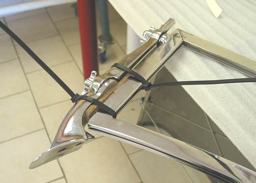 This made it possible to handle the whole assembly with ease and maintain alignment. The groove in the bottom of the windshiled frame is for the rubber strip. Also note that the bottom of the lower stanchion is tapped for bolts (more on this later). |
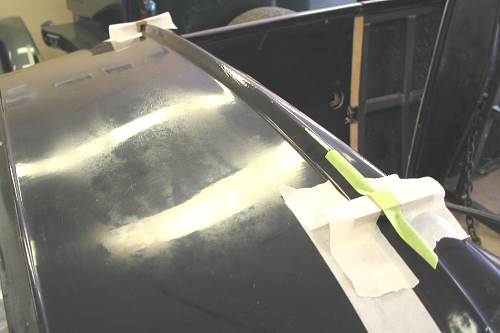 We also taped a couple of spacers to the ridge as a start point in determining height. |
After positioning the assembly a few times, we felt that we were in a position to settle on the final location. The final location had to consider both horizontal orientation and vertical orientation on the pads. Vertically, it ended up being slightly lower than ideal and, as a result, we couldn't get a consistent gap between the frame and the ridge. As we had good horizontal orientation, we concluded that we would proceed regardless and deal with the gap during the bodywork stage. To finalize the location, we masked off the pad area and moved the assembly in place including the rubber insulators. Once positioned, we traced around the insulators. After removing the assembly, we positioned the insulators once more and used the holes in the insulators to determine a starting position for fasteners. |
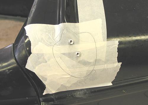 This shows the tracing around the insulators. The holes in the insulators were used to get a "directional" positioning for the fasteners. Pilot holes have been drilled at this point. |
As provided, the lower stanchions are tapped to receive two bolts that are meant to be fed from the underside. Our body was fitted with a curved plate beneath the pad area - the curve not being ideal for fastening to. Further, as we will be putting a top on the car, the stanchions must be very secure. After some additional consideration, two decisions were made:
|
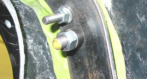
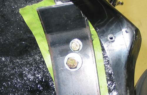 At this point, the pilot holes through the top side were made larger and the bolts are in position. Because of the curve in the plate, the washer does not sit flat. We used this fastening method temporarily to check overall positioning. |
 |
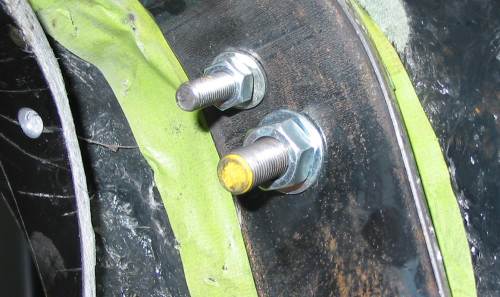 At this point, the bolts have been replaced by high strengh studs. |
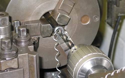 Dream Machines opened up some tube to accept the studs after which the tube was cut to length and bevelled on one end to sit against the plate. |
 This photo illustrates the tube for the larger stud before welding. |
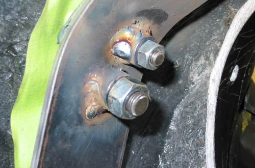 Both tubes have been welded to the curved plate. When tightened, everything pulls into the correct poistion. |
| To complete the under-dash work, Dream Machines added a support that runs between the tops of the curved plates. This will prevent the plates from shifting when the nuts are tightened and adds rigidity. The curved plate will receive further reinforcement when the dash support bracket is added. |
 Note: In order to access the curved plate area, we removed the dash/lower dash support. The dash support comes from the manufacturer welded to the steel upright that the curved plate is welded to. We'll be making the dash / lower dash support a removeable piece in the next article. |
Resources: |
| Next Up - Dash, steering column and linkage |
<< Previous
Article -- Next Article>> |