| Dash Support
/ Steering Column & Linkage |
By Frank Colgoni In a footnote to the previous article dealing with the windshield installation, we mentioned that we had removed the dash and lower dash support to gain access to the under-dash area. Being welded in, the lower dash support prevented removal of the dash. We had determined that a removeable dash / lower dash support would not only facilitate windshield installation but also a number of other components that were slated for the dash / under dash area: heater, electrical components, hood release handles, switches, column support, etc. It would also permit us to work in that area with the support in place but without the dash in place. To begin the process of making things removeable, the dash panel was re-fastened to the cowl with screws and the lower dash support, that we had cut out, was slipped in from behind. The support was then clamped to the dash and the whole assembly was clamped to the body at each side. After examining the area behind the dash at the far corners, our best solution would provide a mount for the lower dash support and provide reinforcement for the curved plate that anchors the lower windshield stanchion (see previous article). |
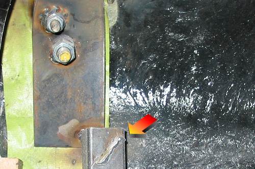 The arrow indicates the weld residue where the lower dash support tab had been welded. The square tube is part of the cowl structure. At this point, the windshield stanchion mounts are complete and the top of the curved plate is reinforced side-to-side (once again, see previous article for details) |
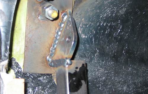 A plate has been added by Dream Machines to the curved plate / top of the square tube. It has been drilled to accept a bolt that will be fed through the back side. The angle of the plate is critical to align with the dash support. |
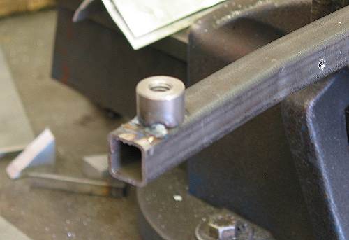 At each end of the dash support, a tapped tube was added to accept the bolt previously mentioned. After test fitting, it will be finish welded. |
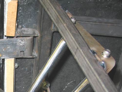
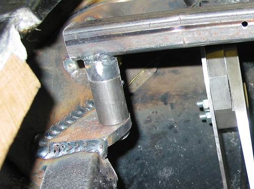 This view from below shows the dash support bolted to the plate. A spacer has been added to maintain fore/aft location. |
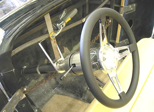
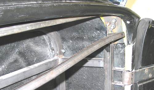 This is what the lower dash support looks like installed. It will come out and go in many times before the car is done. |
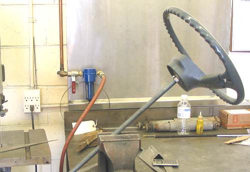
With the dash support resolved, we could turn our attention to determining column location / column selection. Column selection, like most everything else, is a matter of personal taste, theme and function. There's lots of choice out there from columns with no tilt / no signals / no horn wiring to full-featured columns with tilt, a telescopic function and column shift. And, you can get them in paintable steel, brushed and polished aluminum and chrome plated. If you're looking for a column, check out www.ididit.com. They've been manfacturing columns and winning awards for their contribution to rodding since the early 80's. While at their site, check out the "History of ididit inc." for the story behind the company name. |
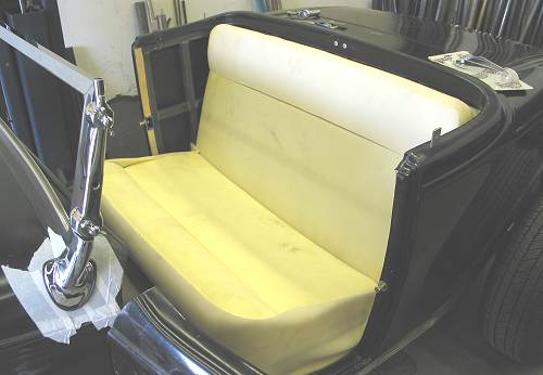
It should also be noted that we had our seat frame and seat foam in place when we decided on column length, exit position on the firewall, the amount that the column would protrude and drop (from the dash). |
 |
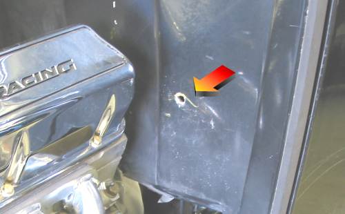 After a considerable amount of positioning, repositioning and discussion, a hole was drilled. Seem high on the firewall? Read on. |
| John at Dream Machines then simulated the route of the steering linkage in considerable detail to ensure that the geometry would work from this height and side-to-side position. This was done before finally committing to the location where the column would exit. It was decided that this would work and a materials list was developed for the linkage. We specified unpolished stainless for these parts:
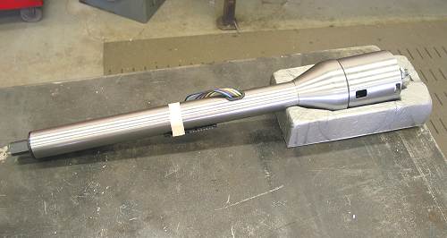
Regarding the actual column, we decided on a paintable column with tilt. The reason for the tilt was to provide for variable driving positions and to ease entry and exit from the car. In terms of length, we settled on a 28" column (ididit # 1120280010). If your first impression is that 28" seems short for a '32 application, it may be if the column exits low on the firewall. To maximize foot room in our roadster, the exit position was moved up the firewall. This accounts for the shorter length. |
 |
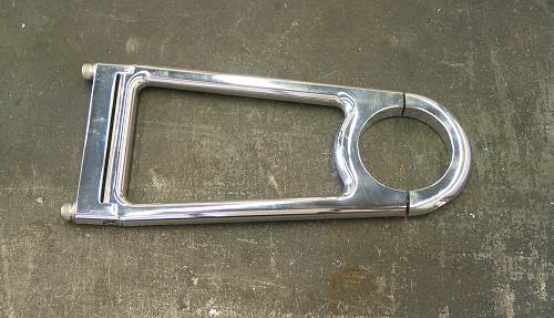 We chose a Mullins 7" open column drop (913207) to hang the column. |
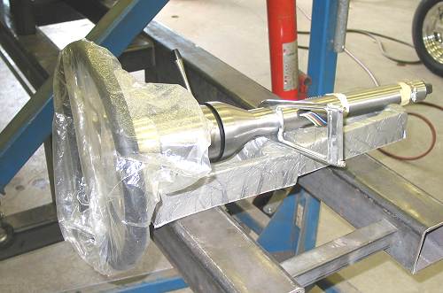 In preparation for hanging the column, everything was assembled. |
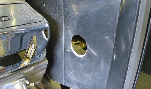 The correct diameter hole was opened up in the firewall. It was subsequently bevelled after column drop was re-established. |
 In the car, the assembly was positioned using a temporary strap that was attched to the column with a radiator hose clamp. We had already established a height using our dummy setup. We confirmed it at this stage. |
 This is a detail shot of the bracket for the column drop. Dream Machines added "ears" to the end of the bracket which act as gussets. |
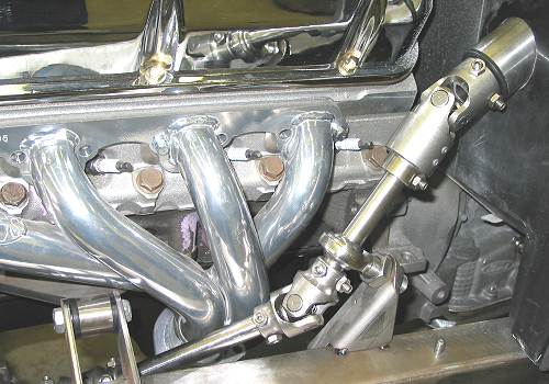
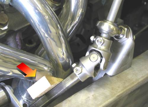 With the column in place and supported, attention could be turned to the linkage once again. In this photo, some dummy shafting is being used to establish the final positioning of the support bearing and the bearing bracket fabricated by John. The arrow indicates a small wooden wedge acting as a spacer between the shaft and header tube. |
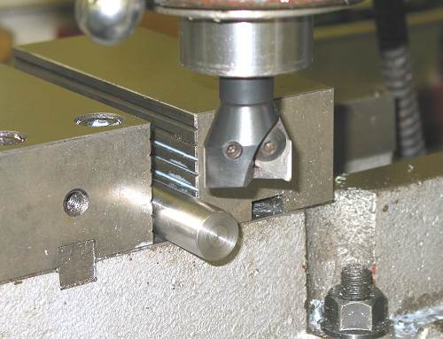 After final positioning was determined, two shafts were cut. John is preparing to "D" the shaft on the mill. The photo below shows the result. |
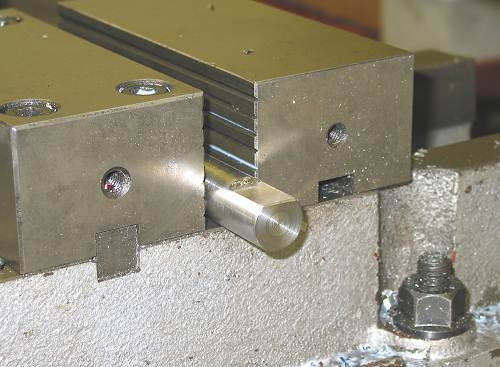 |
 With shafts fabricated, the linkage assembly was installed and the support bearing bracket was tacked into position. |
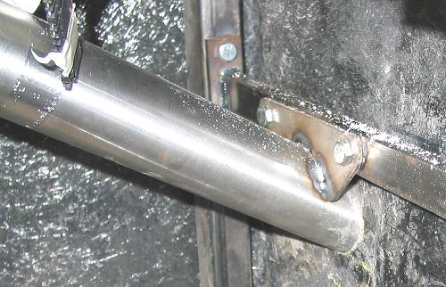 To complete the installation, a lower column mount was added. To facilitate this, and to avoid bolting through the firewall, a removeable transverse rectangular tube was added between the cowl steel uprights and a bracket added to the column. |
Resources: |
| Next Up - Dash / Gauges |
<< Previous
Article -- Next Article>> |