
| Gauges |
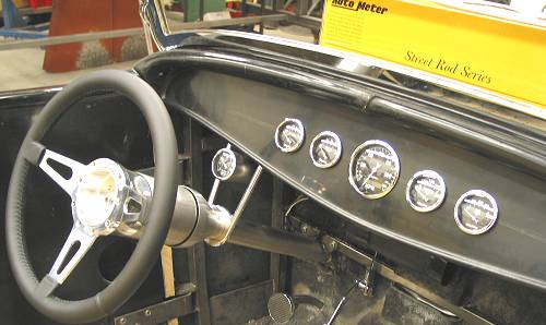
By Frank Colgoni When planning for gauges, and our dash layout, we pictured a very traditional layout accompanied by a clean dash - specifically, nothing other than the gauges. From a style perspective, we found exactly what we were looking for in the Autometer Street Rod Old Tyme Series in black. Their #1709 kit included the gauges that we needed for our layout. That is, electronic speedo, fuel, voltmeter, temperature and oil pressure. These are great looking gauges that suit our theme perfectly with their simple white-on-black colour scheme and domed lenses. While we wanted a tach to complete our instrumentation, we didn't want the tach on the dash as it would increase the overall width of the gauge area. We did a quick mockup using paper templates (3 1/8 in. for the speedo and 2 1/16 in. for the four smaller gauges) with the speedo centered in the dash flanked on each side by two gauges. The proportions seemed just right for the '32 dash. Regarding a tach, Autometer had a choice of either a 3 1/8 in. or the smaller 2 1/16 in. While the 3 1/8" size is the usual choice for remote tach mounting in hot rods and performance applications, we decided on the 2 1/16 in. (#1797) to make it less obtrusive. At this point, we had not decided where to mount it. When we received our gauge package, the gauges were arranged in the box as we had laid them out with our paper templates. The layout was so similar, in terms of the distance between the gauges, that we were able to use part of the packaging as our template for final placement. After confirming vertical and horizontal centerlines, the template was taped to the dash and gauge holes were drilled. Simple as that. |
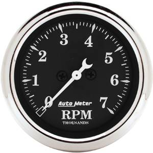 Autometer Street Rod Old Tyme Series Black |
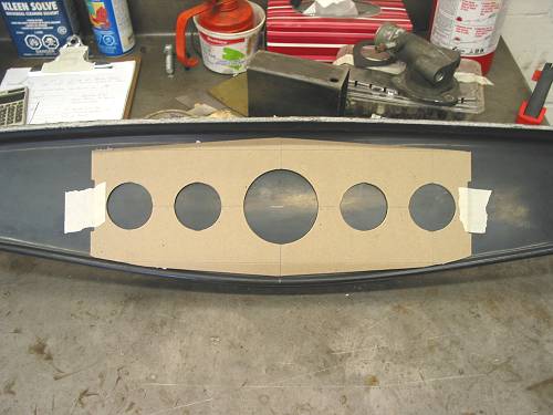 Packaging piece used as template |
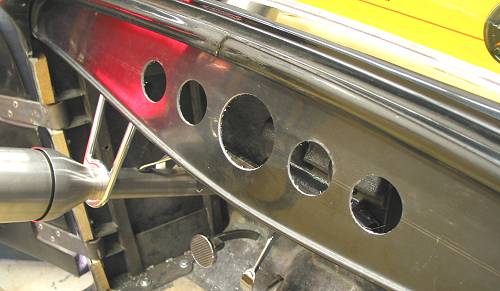 Dash after drilling and installation |
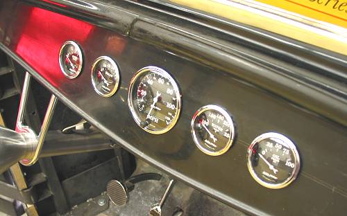 With gauges in place - clean and simple |
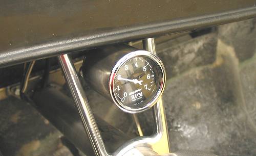
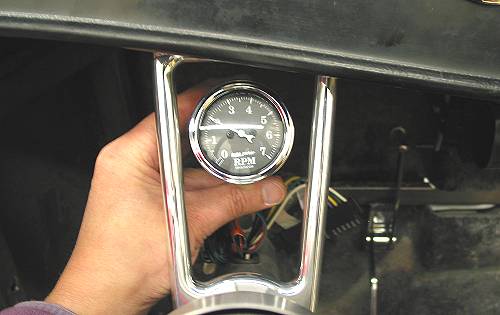 Moving on to the tach, we tried a few different positions but the natural position, given the size of the gauge, was centered in the column drop cutout close to the dash. |
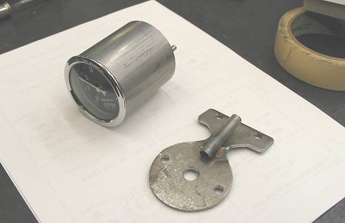
In order to get the face of the tach out far enough (toward the driver) while hiding the tach body and wiring, a custom tach mounting cup would be required. After determing the length of cup required, and cutting a piece of tube to that length, Dream Machines removed material from the inner wall of the tube on the lathe until the gauge would slip in. |
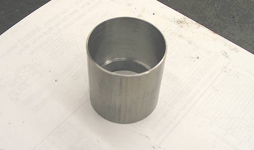 Tach cup taking shape |
| To mount the tube, a bracket was required. A piece of plate was cut to match the width of the tube and "bent" at an angle determined by the back side of the column mount bracket and the required tilt of the tach.
The plate was drilled to accept the tach mounting studs and a hole was drilled to allow the wiring to pass through. To mount the plate, the column drop had to be removed so that the mount portion, above the swivel, could be drilled and tapped to accept small bolts entering form the back side. The tach mounting plate was correpsondingly drilled. |
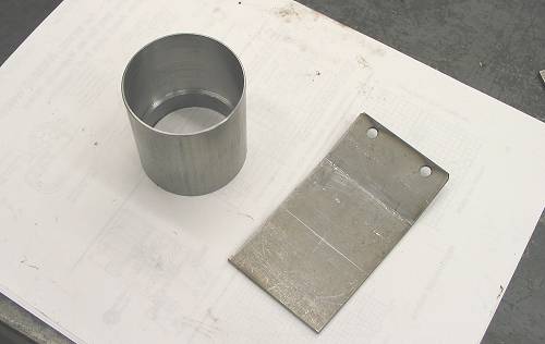 Cup and bracket in progress |
 Test fit before trimming bracket |
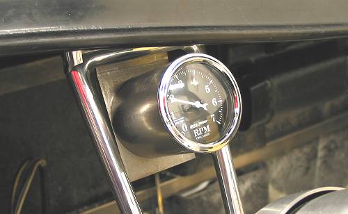
| The plate was then shaped to provide a round mounting surface and a small "neck" area. To complete the mount, Dream Machines added a small tube to the backside of the plate to keep the wires tidy. When mounted, the neck almost disappears giving the impression that the tack is floating. |
 Bracket complete except for final shaping/finishing |
 |
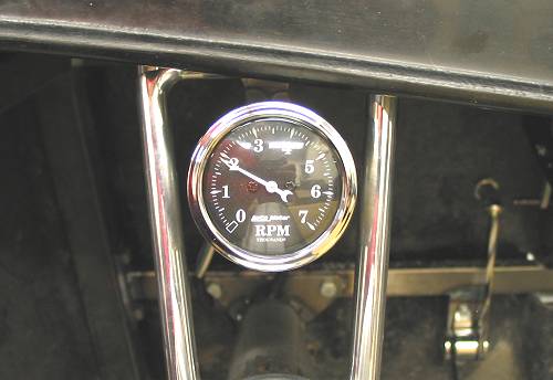 Installed. You'd think the column drop was made for it. |
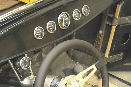 Complete gauge setup (and below from opposite side). |
 |
Happy 50th. Autometer  |
Resources: |
| Next Up - Catching Up |
<< Previous
Article -- Next Article>> |