| Wiring |
| By Frank Colgoni |
This article will outline what was used to wire the car and various in-progress photos. The car was expertly wired by John Edwards of Dream Machines. The main component was a Highway 15 kit from American Autowire supplemented by a series of other American Autowire products such as courtesy light kits, door jamb switches, relays, master disconnect, battery feed stud, indicator LED's, light delay module, weather pac connectors, gauge disconnect kit, etc. Terrific quality materials. |
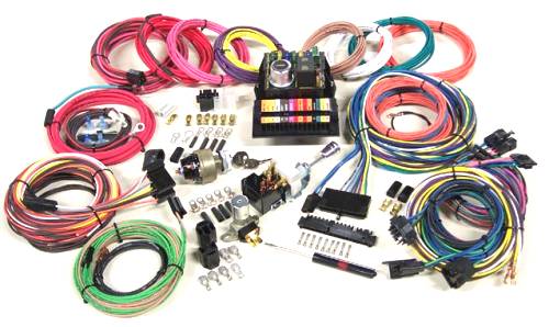 |
| Some features of the Highway 15 kit:
|
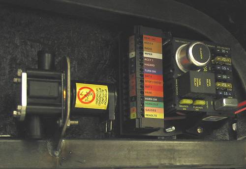 The heart of the matter - the Highway 15 panel that has been mounted in the upper right hand corner of the under-dash area. Left of it is the Vintage Air flow control valve. |
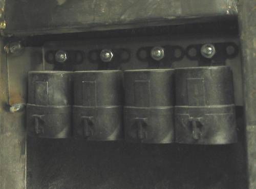 A row of relays in the passenger upper kick panel area.. |
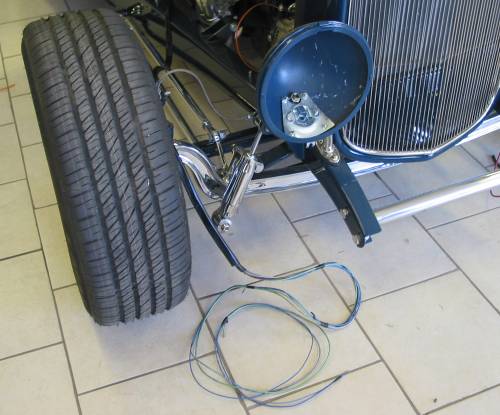
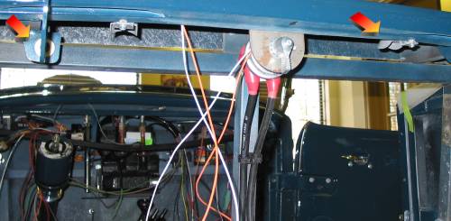
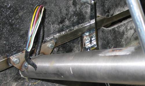 An important wiring detail: Dream Machines relocated the exit position for the steering column wires from the mid column position to the bottom of the column at the firewall to provide a clean column look. |
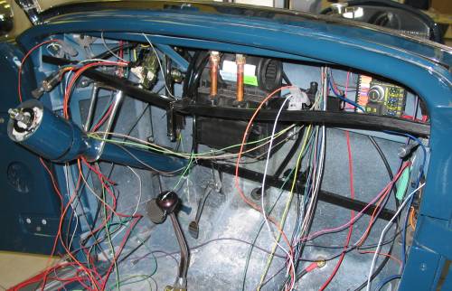 Even a "simple" wiring project involves a lot of wires and connections. John recommends plannning your installation, working methodically, making notes, reading all available literature, following instructions and getting help when necessary. |
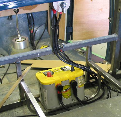
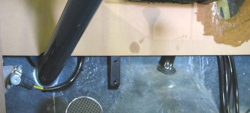
 A battery cable feed stud in the passenger-side floor in the upper left corner. A ground feed stud was subsequently added. |
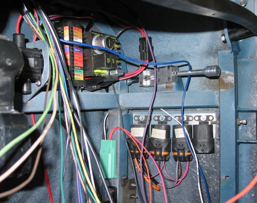 The light blue device to the left of the relays is a courtesy light delay control. |
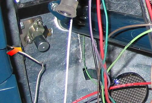 Highbeam control switch to the left of the column. It's high enough as to not interfere with left foot positioning. |
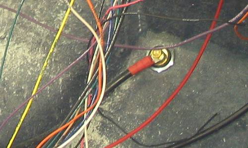
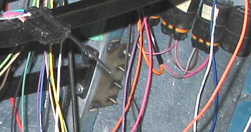 In the centre of the photo is a common grounding plate. |
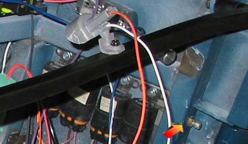 In the upper centre is a front passenger side under dash courtesy light. The arrow points to the door activated switch that triggers the lights. |
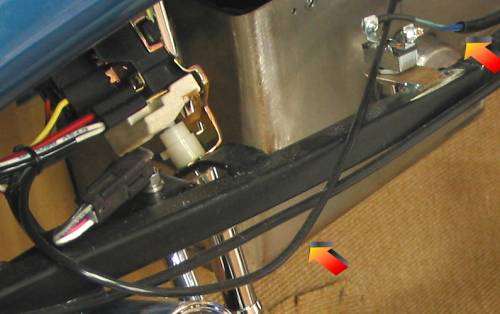
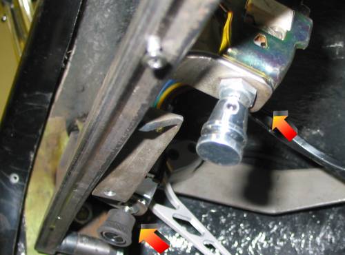 The top arrow points to the headlight switch (right side of the steering column). The bottom arrow points to the heater fan/valve control switch. Both of these are hidden with the dash installed. |
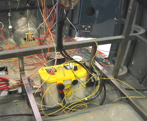
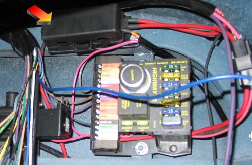 The arrow indicates the 175 amp "Mega Fuse" box. |
|
 Directly above the battery is the master disconnect switch. The right arrow indicates one of two trunk courtesy lights (these were subsequently replaced by trunk side panel lights). The left arrow indicates the courtesy light switch which is activated by the trunk hinge. |
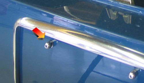 Rear license plate lighting is provided by LED light bolts. |
|
|
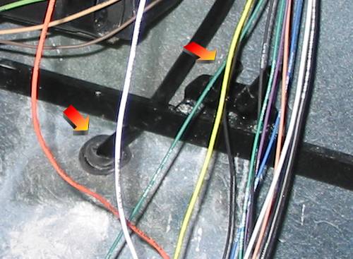
 You can see sleeved wires going to the highbeam switch and, on the right, going down toward the floor towards the rear of the vehicle. |
|
|
Resources: |
| Next Up - Body / Paint |
<< Previous
Article -- Next Article>> |