| Centre Section,
Engine / Tranny Mounts and Rear Crossmember |
By Frank Colgoni We’ve reached a stage in the development of our
frame/chassis, that we can concentrate on the installation of our
main frame crossmember (centre section) and location and mounting
of the engine and transmission. |
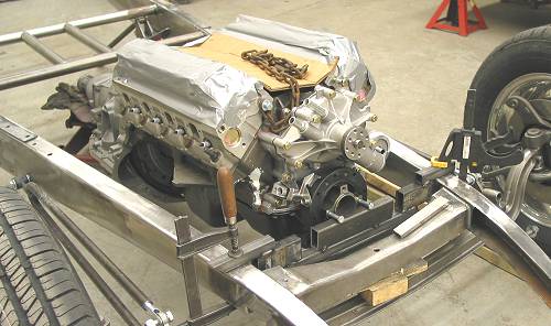
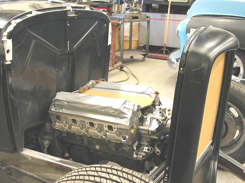 Our engine and transmission are very roughly positioned at this point. |
 Fore / aft clearances are looking pretty good. The bell housing is a bit tight to the tunnel on the driver's side. This will need relieving to achieve the correct height. |
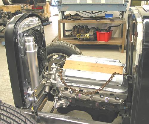
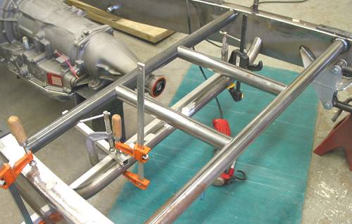
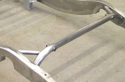
 The upper lateral tubes and braces of our Horton centre section in place. Note: The tranny tailpiece is NOT at its final height in this photo. |
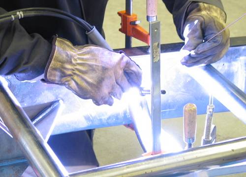
 The engine and tranny fore/aft position have been established. You can see the Welder Series' motor mount plate bolted to the block. |
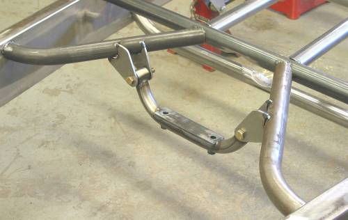
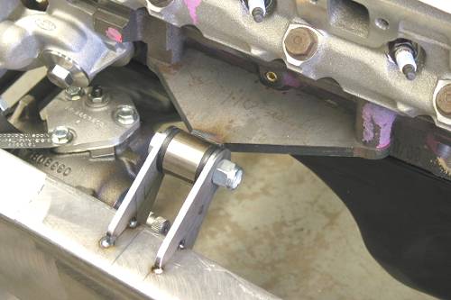 Motor mount in place waiting for final welding. This will be strong and will allow for steering linkage below. You can see the splined steering box input shaft below. |
| With the motor mounts in, John moved on to mount the centre section
lower front tube (which was also notched for driveshaft clearance)
and the front upper tubes. To support the back end of our AOD tranny,
John fabbed a neat tubular cradle-type mount that terminates at urethane-bushed
ends. To complete the centre section, John added the remaining bracing pieces. |
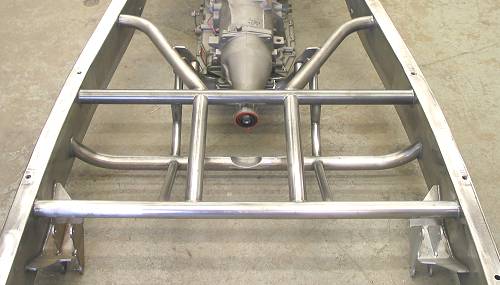
 The lower centre section crossmember is ready to weld. |
|
|
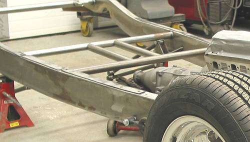
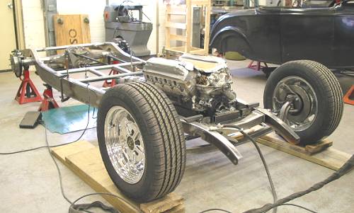 The chassis is coming together. |
 The upper diagonals are in and that effective tranny mount noted above. |
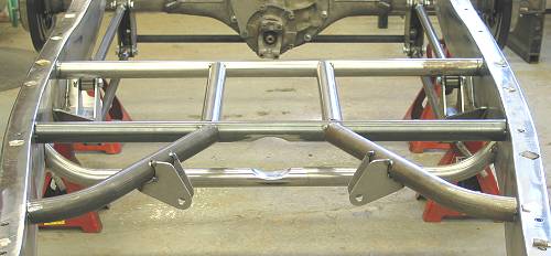 You can see the notched crossmembers in this shot. Everything is done except the bracing. |
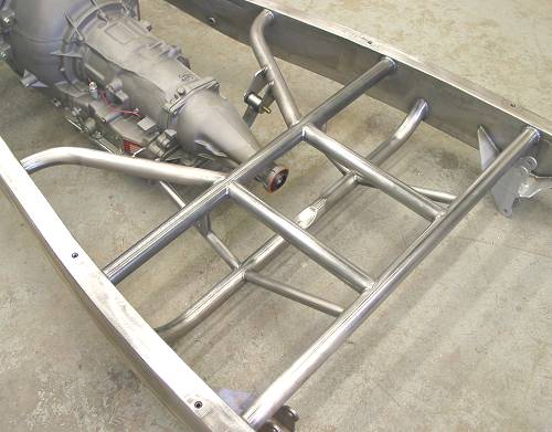 The completed centre section |
 |
| Back in article 5, we said “Unfortunately, our desired ride
height created another problem but we'll save that for another article.”
(revisit article 5 HERE) – time to explain. In article 5, John and I had spent the day making decisions relative to our rear track and the height of our chassis/body as it affects the distance between the top of the tire and the wheel well. This is primarily an aesthetic consideration but one that is important to achieving the right stance. The diameter of the tire factors prominently into the equation. In a coilover spring/shock rear suspension like ours, the height at the rear is a function of the operating length of the coilover (on the optimum angle) combined with the upper and lower mounting positions. That is, the upper being the rear frame crossmember and the lower being the 4-bar axle bracket that doubles as the lower, multi-position, attachment for the coilover. While the multi-positioning of the bracket allows for some fine tuning of ride height, we feel it’s better to place the lower mounting point in a neutral position and then dial in ride height through coilover selection and upper crossmember placement. Herein lies the rub so-to-speak. Once we had decided on our ride height and operating length of our coilover, we realized that the rear crossmember would have to be raised to achieve that desired ride height (in effect lowering the ride height). This would involve not only removing the straight crossmember and replacing it with a raised version but also the trunk floor would have to be altered to accept the raised crossmember. You can see where this is going (er, went that is). As the following photo shows, we lost the straight crossmember and Dream Machines replaced it with a 2” raised version. What we do for the right look… |
 |
Resources: |
| Next Up - Introduction to some products / Our Performance World chassis |
<< Previous
Article -- Next Article>> |