
| Master Cylinder / Booster |
By Frank Colgoni Master Cylinder / Booster Installation (not exactly straighforward) In article 14 of this series, we fussed over placement of the steering column to gain foot room (always an issue) and, before proceeding with locating our master cylinder/booster combo, we had a good look at where we wanted to place our brake pedal (as a standalone item and in relation to our accelerator pedal). With the ideal placement noted, we moved on to the master/booster. In terms of equipment, we're using a CPP Corvette-style dual reservoir master and 7" booster from Horton Hot Rod Parts and a Welder Series pedal and pedal bracket. Having said that, why are we covering this step? We're covering it to share a solution to a problem encountered during installation. Specifically, the best location for the booster also positioned the master in a relatively good spot directly under our flip-up seat cushion but the forward, upper, frame centre section crossmember interfered with the front end of the master cylinder. Dream Machines solved this problem by machining an aluminum spacer to which the master cylinder and booster could be bolted to - allowing the master cylinder to be moved rearward. The spacer's profile allows it to fit under the "offending" crossmember. A longer push rod was also required. Dream Machines took care of that also. While it pushed the master back a little, access to it under the seat remained good. Photos follow: |
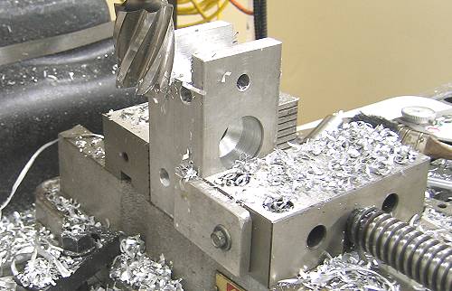 The spacer beginning to take shape in the Dream Machines' mill. |
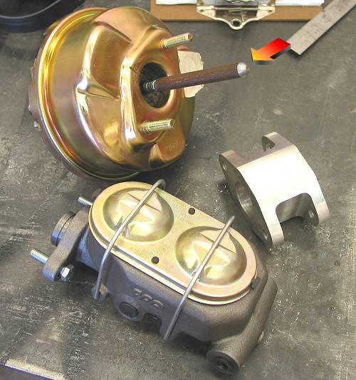 Here's the master cylinder, booster and spacer ready to go. Note the extra-long push rod. |
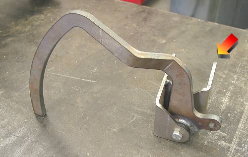 The Welder Series pedal and bracket. Note that there is lots of extra material on the frame side of the bracket for trimming to get exact positioning. |
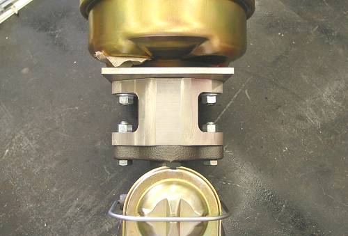
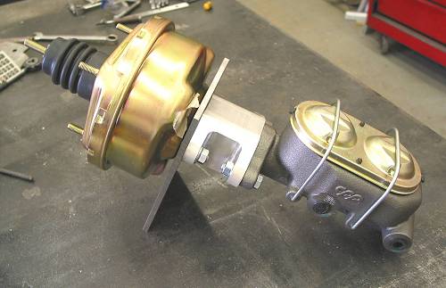 This photo shows the booster, the soon-to-be-bracket, spacer and master bolted together. |
 |
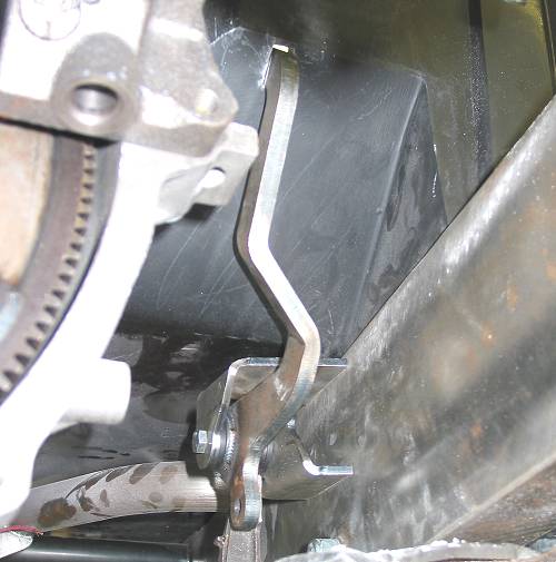 Our pedal / bracket in it's final position. If you compare this photo to the photo of the pedal and bracket above, you'll notice that a significant amount of material was taken off the frame side of the bracket to move it towards the frame rail. This was for exact positioning of the pedal and, not coincidentally, to make room for exhaust to the left. |
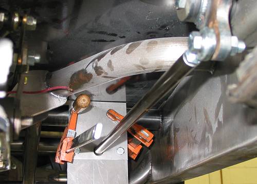 Final positioning of the master/booster bracket is being determined. A pedal to booster push rod follows the route that the booster to master push rod will follow. |
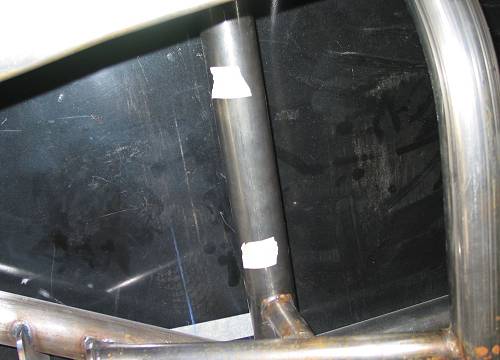 The space delineated by the tape is where the assembly will be positioned. |
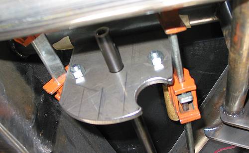 The bracket is ready to be tacked to the crossmember. Dream Machines has shaped the bottom of the bracket and provided a cutout for the booster vacuum fitting. |
 |
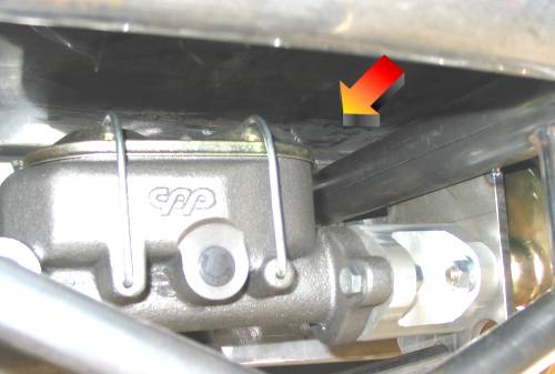
| A lower support leg has been added and the assembly fitted to the bracket. If you haven't noticed yet, note the unconventional placement of the main bracket. That is, between the booster and master rather than off the front of the booster using the mounting studs. |
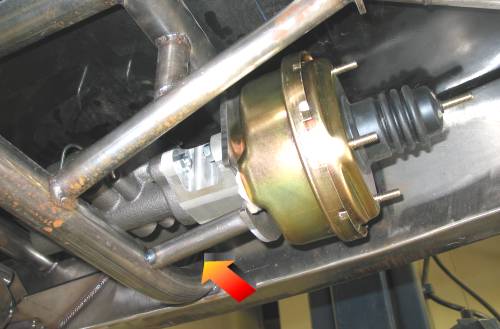
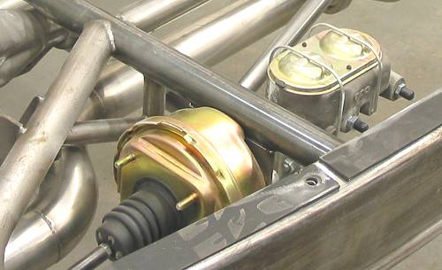
 The arrow indicates where the master cylinder would have encountered the crossmember in absence of the spacer. |
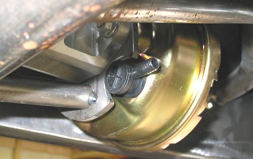 |
 The finished product with the body off. |
Resources: |
| Next Up - Exhaust(ing) Work |
<< Previous
Article -- Next Article>> |