
| Exhaust |
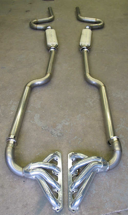
By Frank Colgoni This article will be mostly photos (lots of photos at that) accompanied by the appropriate descriptive text as "a picture is worth a thousand words". Our exhaust system was expertly fabricated by Dream Machines Ltd. using the following components:
Note: The Tri-Clamp system is normally used in applications with a "sanitary" designation (e.g. pharma, bio-tech, food, mineral water, beverage, dairy, cosmetics and allied process industries). As there is no slip fit of any of the components, everything must be quite exact. Once complete, it yields a complete system that is relatively simple to assemble / disassemble. Regarding the Dream Machines' fabricated gaskets, while there are off-the-shelf gaskets that are rated for higher temperatures, we felt that these would not be adequate for the header-to-pipe connection so chose to play it safe and machine gaskets out of bronze - making them bulletproof. So, let's get under way. |
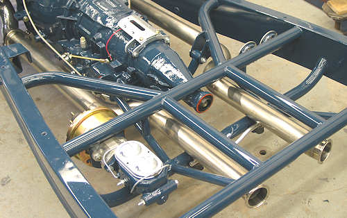
 The blank canvas |
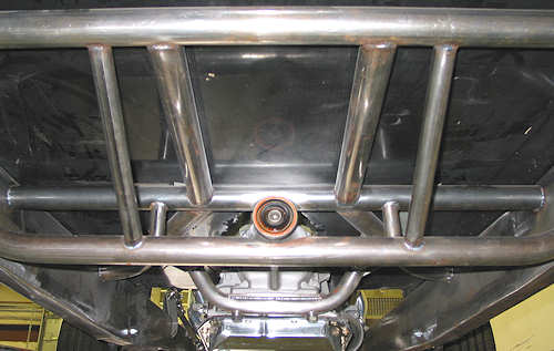
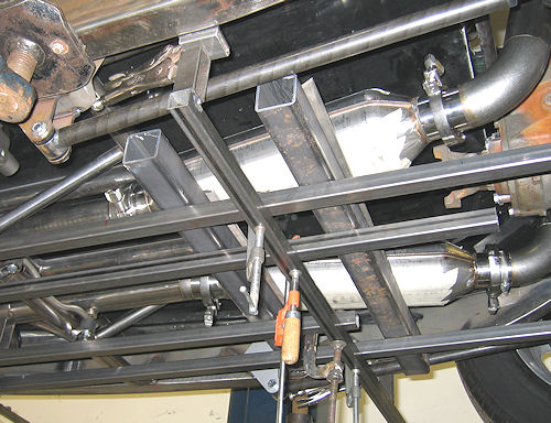
 The reason for this photo is to illustrate the method used by Dream Machines to maintain horizontal alignment of the system from front to back and side to side. Specifically, a fixturing system. |
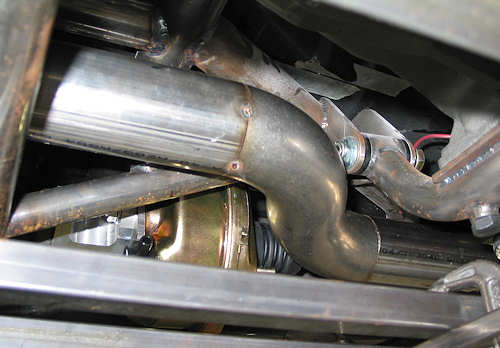
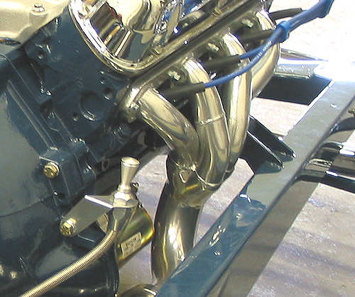
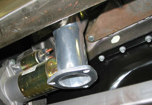 Because of our low ride height, aethestics, and desire to keep the system tucked up as tight as possible, we had to lose the factory collector extension and flange. This is the before photo of the passenger side. |
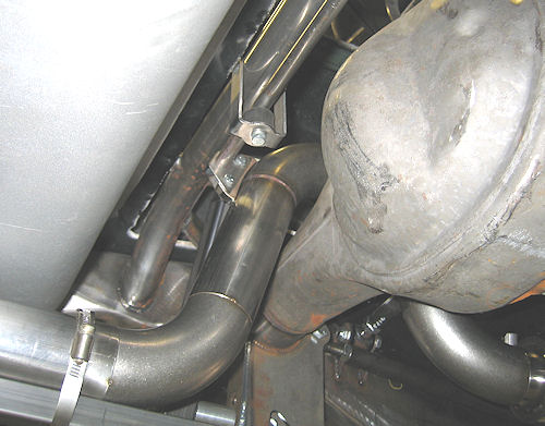
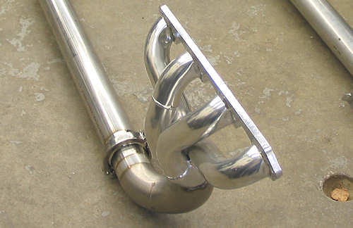
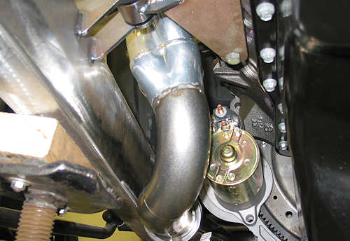 This is the after photo of the same side. Dream Machines cut the header at the collector and made the immediate transition back with 90 deg. SS elbows. In this way, we were going down and back simultaneously. |
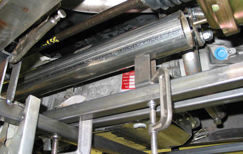
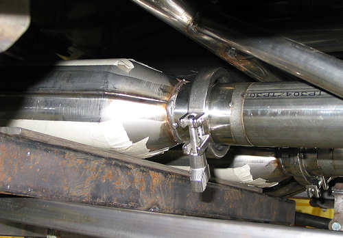
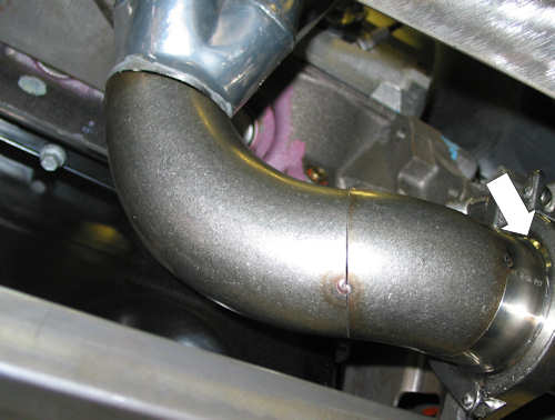 This is a view of the driver's side in an early fitment stage. The arrow is pointing to a Tri-Clamp weld ferrule that will terminate the header instead of a traditional flange, |
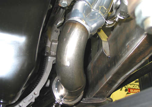 This is another view of the driver's side (frame on right / tranny housing on left). |
 A view from the driver's side looking through the hairpin and under the frame. The turn is nice and tight with the exhaust pipe disappearing where the frame widens. |
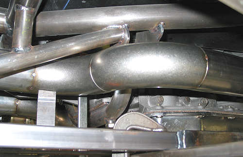 Continuing back, this is the turn going inboard just after the transmission. |
 Ditto, but on the driver's side. |
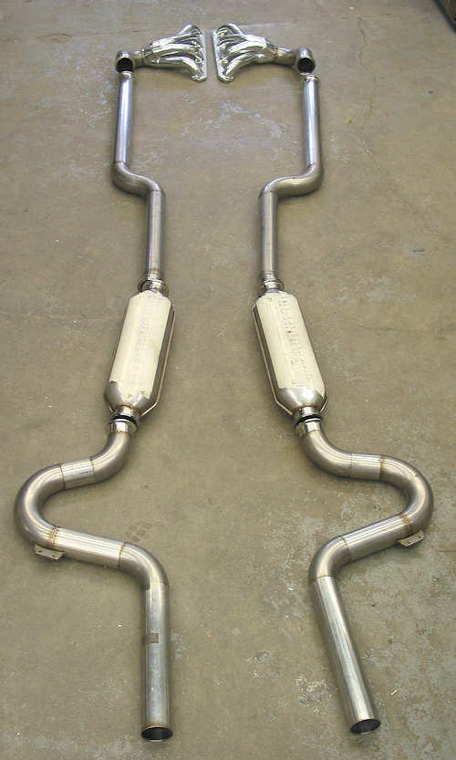
 The connection with the Hushpower muffler. The muffler is stting on part of the fixture that runs side-to-side. From left to right, you're looking at the muffler (to which a weld ferrule has been added in place of the straight tube it came with), the Tri-Clamp, another weld ferrule, a small elbow slice and finally the tube. |
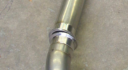
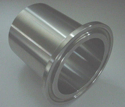 This is an example of a Tri-Clamp weld ferrule (flange). They are available in various O.D.'s and lengths. The groove in the flange face accepts the corresponding profile in the gasket. |
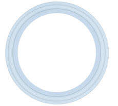 This is an example of a Tri-Clamp gasket. |
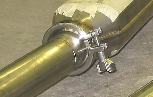 A closer look at the clamp. The clamp is V'd on its interior surface which squeezes the ferrules/flanges together while pinching the gasket. |
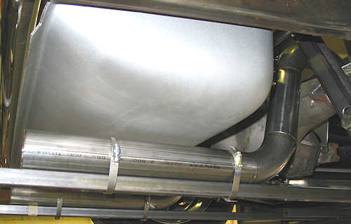
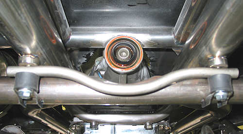
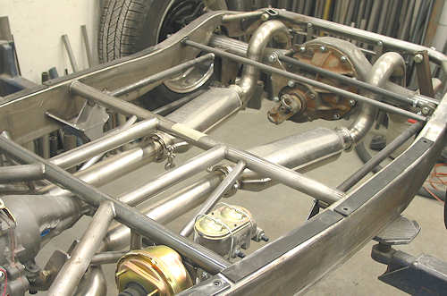
 Up and over the rearend. More on the hanger system in a bit. |
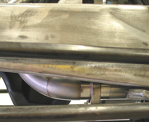
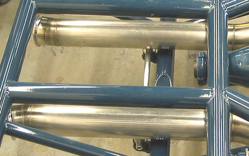
 Finally, in this and the next photo, are the tailpipes which are also fixtured for assembly. |
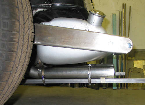 The masking tape on the fixture indicates where the tailpipe will be cut to final length. |
 Additional view of the fixturing below the mufflers. |
 A view of the fixturing shot from the rear. |
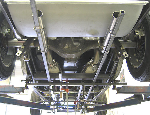
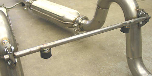
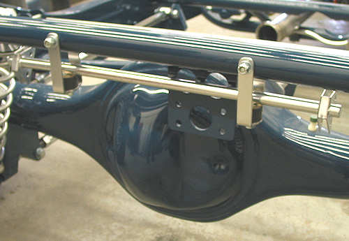
 This is the front hanger system. Notice that the exhaust pipes sit above the insulators rather than hanging from them. The insulators have embedded steel faces and accept a bolt on the bottom and have an integrated bolt on the top. The integrated bolt threads into the small, threaded wafers that have been added to the pipes. Bolts pass through brackets attached to a lower crossmember and then into the bottom side of the insulator. The cross tube acts as a stabilizer to prevent any independant twisting. |
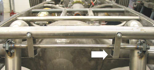 In the rear, tabs were added to the pipes which accept a straddle-bracket. The bracket is attached to the tranverse tube which rests on the insulator (white arrow) which is suspended by hangers. More details further on. |
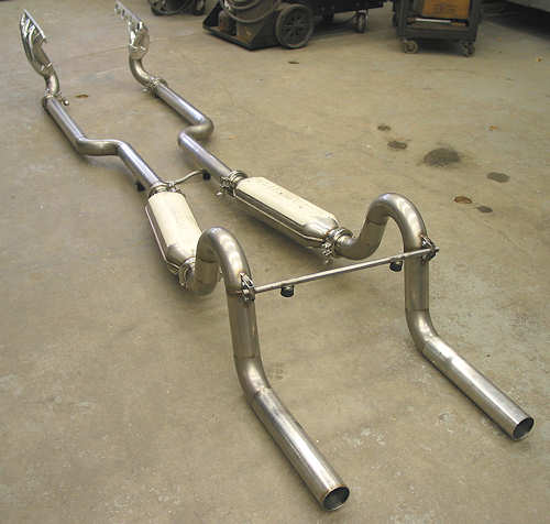
 The completed tacked system from front to back. |
 And, from the back. |
 A joint of two weld ferrules minus gasket and clamp. |
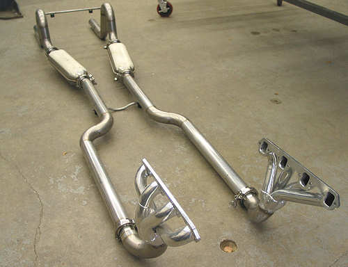 Completed as it will fit on the car. |
 Detail of modified header and first joint. |
 |
 Detail of rear hanger tube with insulators and pipe tabs / brackets. |
 |
 |
 |
 Hanger systems and headers were given ceramic coating by High Tech Coatings of Ruscom, Ontario (near Windsor). Very nice job and great turnaround. |
 |
| Want To Hear It Run? The video clip below was taken at Dream Machines at first fire-up. It'll give you an idea of how the system sounds so turn up your speakers. Near the end of the clip, you'll see the fabricators' reaction (John Edwards of Dream Machines) although it will be hard to hear what he says... |
Resources: |
| Next Up - Body mods |
<< Previous
Article -- Next Article>> |